
|
Paul Risdale has Modified the servos on his Footy in the same way as this article to give a 180 degree throw
The resistors + desoldering braid are available from Maplins .
He used the same technique to extend the throw of the 9g Component Shop servos. There is just enough room to squeeze a couple of resistors into the small recesses between the feedback pot and the motor.
The resistors + desoldering braid are available from Maplins .
He used the same technique to extend the throw of the 9g Component Shop servos. There is just enough room to squeeze a couple of resistors into the small recesses between the feedback pot and the motor.
How to Modify a Futaba S-148
for 180 Degree Operation
to read the original article CLICK HERE
Text and Photos by: Dave McDonald
AMA 40128 ([email protected])
Did you ever need a servo that rotated 180 degrees to run a cheap pair of mechanical retracts? And did you cringe at the thought of spending twice as much money just for that retract servo.....than you paid for your retracts themselves?
Or........
Did you ever wish you had a fully proportional servo that rotated 180 degrees to operate your flaps?......but you couldn't find one anywhere......at any price?
UPDATE:
I think I owe Airtronics an apology here! It has been brought to my attention that the Airtronics 94739 is a 170 degree proportional double ball bearing servo that is similar in size to the Futaba S-148, but with nearly twice the torque.
The Airtronics 94739 servo lists for about 100 dollars with a street price of about 70 dollars.
Thank you Jack Albrecht for bringing this to my attention!
This procedure will explain how to easily modify a standard Futaba S-148 into a servo that travels 180 degrees instead of the usual 60 degrees. But unlike a dedicated retract servo, this modified S-148 will still be fully proportional.
Modifying the electronic circuit only requires adding 2 new resistors to the
S-148 circuitry. It isn't diffiult to do.....BUT......because of the very limited space inside the S-148 servo, and the small size of the S-148 circuit board, I don't recommend that you try this unless you are experienced at soldering and desoldering small electronic circuits.
And now that the disclaimer is out of the way,
here's how I did it: :-)
Materials needed:
You'll only need a total of 2 new resistors for this project.
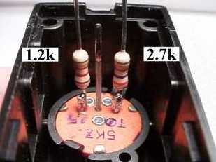
One is a 1.2k resistor, 1/4 watt. (brown, red, red)
The other is a 2.7k resistor, 1/4 watt. (red, violet, red)
Disassembling the Futaba S-148 Servo:
for 180 Degree Operation
to read the original article CLICK HERE
Text and Photos by: Dave McDonald
AMA 40128 ([email protected])
Did you ever need a servo that rotated 180 degrees to run a cheap pair of mechanical retracts? And did you cringe at the thought of spending twice as much money just for that retract servo.....than you paid for your retracts themselves?
Or........
Did you ever wish you had a fully proportional servo that rotated 180 degrees to operate your flaps?......but you couldn't find one anywhere......at any price?
UPDATE:
I think I owe Airtronics an apology here! It has been brought to my attention that the Airtronics 94739 is a 170 degree proportional double ball bearing servo that is similar in size to the Futaba S-148, but with nearly twice the torque.
The Airtronics 94739 servo lists for about 100 dollars with a street price of about 70 dollars.
Thank you Jack Albrecht for bringing this to my attention!
This procedure will explain how to easily modify a standard Futaba S-148 into a servo that travels 180 degrees instead of the usual 60 degrees. But unlike a dedicated retract servo, this modified S-148 will still be fully proportional.
Modifying the electronic circuit only requires adding 2 new resistors to the
S-148 circuitry. It isn't diffiult to do.....BUT......because of the very limited space inside the S-148 servo, and the small size of the S-148 circuit board, I don't recommend that you try this unless you are experienced at soldering and desoldering small electronic circuits.
And now that the disclaimer is out of the way,
here's how I did it: :-)
Materials needed:
You'll only need a total of 2 new resistors for this project.
One is a 1.2k resistor, 1/4 watt. (brown, red, red)
The other is a 2.7k resistor, 1/4 watt. (red, violet, red)
Disassembling the Futaba S-148 Servo:
- Remove the servo arm and hold down screw.
- Remove the (4) bottom case screws, and the bottom case cover.
- Remove the top section of servo case.
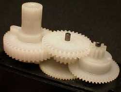
- Remove all of the servo gears from the middle section of the servo case.
- Remove both of the small screws holding the motor to the servo case middle section.
|
|
Modifying the Futaba S-148 Servo
for 180 Degree Rotation:
for 180 Degree Rotation:
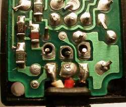
- Locate the two outer leads of the feedback potentiometer, and leaving about 1/4 inch of the leads sticking out of the bottom of the feedback pot, cut off the excess leads. (Note: Do NOT cut the center lead!)
- Double check the circuit board to make sure that the three holes in the circuit board are left fully open. De-solder again if necessary. (Note: Solder wick works best!)
- Prepare both new resistors by trimming ONE of the leads off of each resistor down to about 1/4 inch in length. Leave the other lead of each resistor full length.
- Pre-tin the shortened resistor leads on both resistors.
- Pre-tin both of the shortened outer feedback pot leads.
|
|
- Carefully place the motor/circuit board assembly back into the middle section of the servo case by threading the two resistor leads through the two outer holes, and the center pot lead back into the center hole. Push on the motor and circuit board until they are fully seated back into the proper position.
- Re-install the two motor hold down screws.
- Solder the 1.2k resistor lead, the 2.7k resistor lead, and the center lead of the feedback pot to the circuit board, and trim off the excess leads. (Note: Do NOT use too much solder here, or the excess solder could run down inside of the servo, possibly causing a short circuit!)
|
|
CAUTION:
Do NOT allow the modified servo to try to rotate beyond the mechanical limits of the geartrain!!!
If necessary, adjust your transmitter's ATV to avoid over driving the servo!!!
Do NOT allow the modified servo to try to rotate beyond the mechanical limits of the geartrain!!!
If necessary, adjust your transmitter's ATV to avoid over driving the servo!!!
